- 您现在的位置:买卖IC网 > Sheet目录1994 > DS21Q58L (Maxim Integrated Products)IC TXRX E1 QUAD 3.3V 100-LQFP
DS21Q58 E1 Quad Transceiver
19 of 74
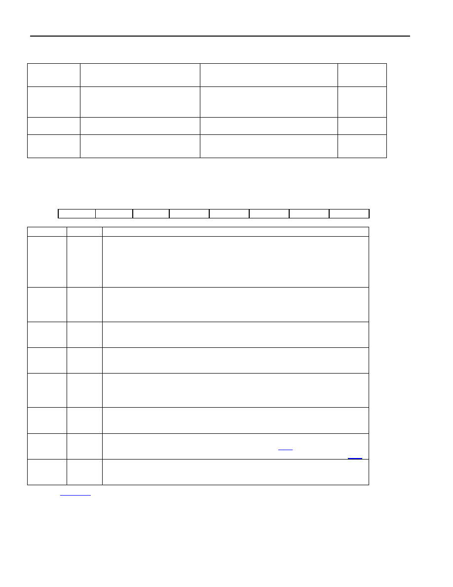
Table 8-1. Sync/Resync Criteria
FRAME OR
MULTIFRAME
LEVEL
SYNC CRITERIA
RESYNC CRITERIA
ITU SPEC.
FAS
FAS present in frame N and N + 2,
and FAS not present in frame N + 1
Three consecutive incorrect FAS received;
alternate (RCR1.2 = 1): if the above criteria
is met or three consecutive incorrect bit 2 of
non-FAS received
G.706
4.1.1
4.1.2
CRC4
Two valid MF alignment words found
within 8ms
915 or more CRC4 codewords out of 1000
received in error
G.706
4.2 and 4.3.2
CAS
Valid MF alignment word found and
previous time slot 16 contains code
other than all zeros
Two consecutive MF alignment words
received in error
G.732 5.2
Register Name:
TCR
Register Description:
Transmit Control Register
Register Address:
11 Hex
Bit #
7
6
5
4
3
2
1
0
Name
IFSS
TFPT
AEBE
TUA1
TSiS
TSA1
TSM
TSIO
NAME
BIT
FUNCTION
IFSS
7
Internal Frame-Sync Select
0 = TSYNC normal
1 = if TSYNC is in the INPUT mode (TSIO = 0), then TSYNC is internally
replaced by the recovered receive frame sync; the TSYNC pin is ignored
1 = if TSYNC is in the OUTPUT mode (TSIO = 1), then TSYNC outputs the
recovered multiframe frame sync
TFPT
6
Transmit Time Slot 0 Pass Through
0 = FAS bits/Sa bits/remote alarm sourced internally from the TAF and TNAF
registers
1 = FAS bits/Sa bits/remote alarm sourced from TSER
AEBE
5
Automatic E-Bit Enable
0 = E-bits not automatically set in the transmit direction
1 = E-bits automatically set in the transmit direction
TUA1
4
Transmit Unframed All Ones
0 = transmit data normally
1 = transmit an unframed all-ones code
TSiS
3
Transmit International Bit Select
0 = sample Si bits at TSER pin
1 = source Si bits from TAF and TNAF registers (In this mode, TCR.6 must be
set to 0)
TSA1
2
Transmit Signaling All Ones
0 = normal operation
1 = force time slot 16 in every frame to all ones
TSM
1
TSYNC Mode Select
0 = frame mode (see the timing diagrams in Section 24.2)
1 = CAS and CRC4 multiframe mode (see the timing diagrams in Section 24.2)
TSIO
0
TSYNC I/O Select
0 = TSYNC is an input
1 = TSYNC is an output
Note: See Figure 24-9 for more details about how the transmit control register affects DS21Q58 operation.
发布紧急采购,3分钟左右您将得到回复。
相关PDF资料
DS2404B
IC ECONORAM TIMECHIP 5.5V 16SSOP
DS2415P+T&R
IC TIME CHIP 1-WIRE 6-TSOC
DS2417X/T&R
IC TIMECHIP W/INTRPT 1WIRE CSP
DS26502LN+
IC T1/E1/J1 64KCC ELEMENT 64LQFP
DS26503LN+
IC T1/E1/J1 BITS ELEMENT 64-LQFP
DS3105LN+
IC TIMING LINE CARD 64-LQFP
DS3106LN+
IC TIMING LINE CARD 64-LQFP
DS3231MZ+
IC RTC I2C 8SOIC
相关代理商/技术参数
DS21Q58L+
功能描述:网络控制器与处理器 IC Quad E1 Transceiver RoHS:否 制造商:Micrel 产品:Controller Area Network (CAN) 收发器数量: 数据速率: 电源电流(最大值):595 mA 最大工作温度:+ 85 C 安装风格:SMD/SMT 封装 / 箱体:PBGA-400 封装:Tray
DS21Q58LN
功能描述:网络控制器与处理器 IC RoHS:否 制造商:Micrel 产品:Controller Area Network (CAN) 收发器数量: 数据速率: 电源电流(最大值):595 mA 最大工作温度:+ 85 C 安装风格:SMD/SMT 封装 / 箱体:PBGA-400 封装:Tray
DS21Q58LN+
功能描述:网络控制器与处理器 IC Quad E1 Transceiver RoHS:否 制造商:Micrel 产品:Controller Area Network (CAN) 收发器数量: 数据速率: 电源电流(最大值):595 mA 最大工作温度:+ 85 C 安装风格:SMD/SMT 封装 / 箱体:PBGA-400 封装:Tray
DS21Q59
制造商:MAXIM 制造商全称:Maxim Integrated Products 功能描述:RELIABILITY REPORT FOR DS21Q59, REV A2
DS21Q59DK
功能描述:网络开发工具 DS21Q59 Dev Kit RoHS:否 制造商:Rabbit Semiconductor 产品:Development Kits 类型:Ethernet to Wi-Fi Bridges 工具用于评估:RCM6600W 数据速率:20 Mbps, 40 Mbps 接口类型:802.11 b/g, Ethernet 工作电源电压:3.3 V
DS21Q59L
功能描述:网络控制器与处理器 IC Quad E1 Transceiver RoHS:否 制造商:Micrel 产品:Controller Area Network (CAN) 收发器数量: 数据速率: 电源电流(最大值):595 mA 最大工作温度:+ 85 C 安装风格:SMD/SMT 封装 / 箱体:PBGA-400 封装:Tray
DS21Q59L+
功能描述:网络控制器与处理器 IC Quad E1 Transceiver RoHS:否 制造商:Micrel 产品:Controller Area Network (CAN) 收发器数量: 数据速率: 电源电流(最大值):595 mA 最大工作温度:+ 85 C 安装风格:SMD/SMT 封装 / 箱体:PBGA-400 封装:Tray
DS21Q59LN
功能描述:网络控制器与处理器 IC Quad E1 Transceiver RoHS:否 制造商:Micrel 产品:Controller Area Network (CAN) 收发器数量: 数据速率: 电源电流(最大值):595 mA 最大工作温度:+ 85 C 安装风格:SMD/SMT 封装 / 箱体:PBGA-400 封装:Tray